Draw A Use Case Diagram For Student Registration System
Comprehensive guide to Use Case Diagram including its components, benefits, and examples, etc. Also learn the step by step directions to draw Use Case Diagrams:
Any real-world system has multiple users and representation of the system should consider the perspective of all users. UML (Unified Modeling Language) is a visual representation of a system. The system can be software as well as non-software application.
Software UML diagrams present different perspectives of the system, mainly the design, implementation, process, and deployment. It is referred by software personnel, business users, and all interested in understanding the said system.
A Use Case diagram is a UML diagram that represents the dynamic model of the system and is referred to as a 'Behavior diagram' describing the system.
What You Will Learn:
- What Is Use Case Diagram
- Objective Of UML Use Case Diagrams
- Benefits
- Components
- Multiplicity Of Use Case And Actor
- Relationship: Exclude And Include
- To-do List Before Drawing Use-Case Diagram
- Project Document Sample
- Draw Use Case Diagram: Step-by-Step Guideline
- Use Case Diagram Examples
- Frequently Asked Questions
- Conclusion
- Recommended Reading
What Is Use Case Diagram

Use Case diagram represents the system's functionality connecting all four perspectives, i.e. design, implementation, process, and deployment. For every single functionality representation, a fresh diagram is used. Hence multiple use case diagrams represent the complete system.
Objective Of UML Use Case Diagrams
The main purpose is to present all functional requirements of the system diagrammatically with all the users who can access the functionality. The presentation is from the perspective of all users giving a high-level design and basic flow of events of the system.
It represented the collaboration and interdependence of the functionality and users in a very easy and understandable manner. The observable outcome of the functionality to the actor and other stakeholders of the system is shown with clarity.
It also presents the functionality's exceptions, pre-condition, and post-condition. The diagrams do not give the details of deployment, trigger of the event, etc.
Benefits
The benefits are as follows:
- Use Case diagram is a functional requirement documentation technique. It elicits the functionality as a black box with all the users who have access or a role in it.
- They are presented in a simple and non-technical way, easy to understand by all technical and business users.
- They bring customers, and all other users on the same page, making communication easy.
- It presents a large complex project as a set of small functionalities.
- It is presented from the end user's perspective, making it easy for the developers to understand the business purpose.
- The association presented between actors and other external applications brings clarity to the validations and checking required for the wholesome verification of the system.
- Use Case driven project development and tracking approach helps in assessing the progress of the project from a functionality readiness point of view. The key development activity status enables the project heads to present the readiness from a customer deliverable point of view.
- The project development can be prioritized as per key deliverable functionalities facilitating better control and management of project revenue.
Components
Listed below are some important components of Use Case diagrams:
#1) System: It is also referred to as scenario or functionality. It details a set of actions between actors and the data consumed and produced if any. Notation of System Boundary (Subject) is a rectangle with System's name on top of the rectangle.
All use cases or functionality of the specific system are located inside the rectangle. The actors accessing the system are placed outside the system boundary.
#2) Use Case: It represents a functional unit of a large application. Notation is horizontally shaped oval and is located inside the System boundary rectangle indicating that the use case applies to the mentioned subject. A specific use case can be referred to by other systems as well.
So the system is not the owner of the use case. The interactions and action between events, actors, and the data lead to the end result that is the Use Case goal.

#3) Actor: Actor is the entity that interacts with the subject. Actor is external to the subject and hence lies outside the system's boundary. Actor's naming should represent the role they play in the system, e.g. Customer, Student, Web-User, etc. Notation is the "stick man" icon with the actor's name above or below the icon.
Custom icons can also be used to denote actors to represent the actor with more clarity. The actor using the use case services is called the primary actor and the actor maintaining or providing services to the use case is called the supporting actor.

#4) Relationship and Associations: The actors and use cases have an association with each other. The notation, a line with an arrow, shows a generalized relationship between the two components. In the example below 'Registered-User' and 'New-User' are generalized to 'Web-Browser'.
A line between the use case and an actor denotes a communication link between them. Association between actors and use cases can only be binary. A use case can be linked to multiple actors and an actor could also be associated with multiple use cases.

Suggested Reading =>> Entity-Relationship Diagram tutorial
Multiplicity Of Use Case And Actor
Multiplicity of Use Case:
When a use case can be associated with multiple Actors, then it's a case of multiplicity of a use case. For example, as shown in the above image "Notation- Relationship And Association", View-Courses' is associated with two actors–'New-User' and 'Registered-User'.
Multiplicity of an Actor
#1) Multiplicity of an Actor is an association represented by a number and can be zero to any number.
#2) Multiplicity zero – It means the use case may have an instance of no actor.
#3) Multiplicity One – It means one actor is a must for the use case.
#4) Refer to the diagram of 'Online Training Website' explained below:
- When the course payment use case is processed through cash payment, the bank payment service will not be required. Hence multiplicity of actor 'Bank-Payment-Service' can be 0.
- For accessing 'View-Course' one actor 'New-User' is a must hence multiplicity of this association is 1.
#5) Multiplicity greater than 1 – means there can be multiple actors involved in a use case instance. Multiple actors can be associated concurrently or at different points of time or sequentially.
- Multiplicity of an actor more than one is rare. Consider a use case diagram of a marathon-race game where multiple players run concurrently in a given instance of race. So Multiplicity of the actor (player) will be greater than 1 and concurrent.
- Consider a use case diagram of a chess game. Two players will be associated but sequentially as the steps taken by each player is not in parallel but in sequence in an instance of a chess game.
- In a use case diagram depicting the activity of a single relay-race team, multiple players will be associated but at different points in time. In an instance of race, all team members of one team are active at a different point in time.
Relationship: Exclude And Include
Relationship Extend
- Extend is a relationship between two use cases. One is called the extended use case and the other extending use case.
- It is a directed relationship from the extending to the extended use case.
- The extended use case is independent and complete on its own and is the owner of the extend relationship.
- The extending use case has no relevance independently, and it just adds value to the extended use case.
- Notation is a dashed line with an open arrowhead labeled with the keyword «extend».
- The Extended Use Case name can have names of all its extending use cases as well.
- A specific use case can be extended by more than one use case.
- The extending use case can be extended further also.
- The condition which triggers the extension use case and the detail of the extension point is mentioned in a comment note and is optional
Relationship Include
- Include relationship between use cases denote that the behavior of the included use case is part of the base use case
- Include helps in breaking a large use case into smaller manageable use cases. A base use case can have multiple included use cases.
- Include also helps in not repeating a specific behavior, which is commonly referred to by different use cases.
- The common part is depicted in the included use case and is associated with all the use cases where it is referred.
- The including use case needs the included use case for completion. So Include cannot be depicted alone.
- Notation is a dashed-arrow with arrowhead from the including base use case to the included common part use case. The relationship notation is labeled with the keyword «include»
- An included use case can include another use case. Refer to Example 3 shown below in this tutorial, where Search doc includes Preview doc, which includes Browse docs.
Refer to the diagram of 'Online Training Website' explained below:
- For joining a course, the user needs to search the course, select it and make payment. Hence the two use cases 'View-Courses' and 'Course-payment' are included in 'Join-a-Course' use case.
- 'View-Courses' can be accessed by actor 'New-User' and also 'Registered-User'. Hence the use case is separated to enable access to two actors.
- 'Course-payment' is separated to make the base use 'Join-a-Course' less complex.
For better understanding of all the components, please refer to the section "Step by step Guideline to Draw Use Case Diagram".
To-do List Before Drawing Use-Case Diagram
Listed below are some readiness points before starting to draw a use case diagram to represent a System:
#1) Project break down into multiple small functionalities
- Understand the complex large project and break it down into multiple functionalities and start documenting the detail of each functionality.
#2) Identify the goal and prioritize
- Start listing each functionality identified with the goal to be achieved by the functionality.
- Prioritize the identified functionality as per the business deliverable plan.
#3) Functionality Scope
- Understand the scope of the functionality and draw the system boundary.
- Identify all the use cases that need to be part of the system to achieve the goal.
- List all the actors (users and services) that have a role in the system. An actor can be a human, internal, and external application that can interact with the functionality.
#4) Identify relationship and association
- Have clarity in the relationships and interdependency between use cases and actors.
#5) Identify Extension and Inclusion Use cases
- List all the use cases with extension or Include a use case for it.
#6) Identify Multiplicity
- Find multiplicity of Use cases and Actors, if any.
#7) Naming Use Case and actors
- Follow a standard in naming the use cases and actors. The name should be self-explanatory.
- The name referred for a specific user/use case should be the same across the whole project.
- A brief detail of use case functionality and the actors with access to the use case should be summarized under a specific section in the document.
#8) Important note points
- Clarify and highlight important points using Notes without overburdening the use case with notes.
#9) Review
- Review and validate the document before starting the drawing of the use cases.
The drawing of a specific system Use Case diagram should start only after the above details are documented and approved. An approved system's drawing can be started while the overall project's details are still being gathered and documentation is in progress.
Project Document Sample
Refer to the Sample document prepared which is a deliverable.
- The document helps in preparing for the Use Case depiction of the system, scheduling the Use case drawing, tracking the progress of the development, etc.
- The 'List of System' enables to schedule the System that can be picked for Use Case drawing, i.e. one whose status is approved.
- The 'List of Use Cases' and 'List of Actors' detail the use cases and actors in the scope of the system.
Document Sample
Project Name: Online Training Website
List of Actors of the Project
List of Use Cases/Activities
List of System (Functionality list)
Draw Use Case Diagram: Step-by-Step Guideline
The current section explains the step-by-step approach to draw Use Case diagram. Refer to the 'Document Sample' and select the 'System' with status – Approved i.e. 'Online Training Registration'. Change the status to Use Case Diagram 'started' to facilitate progress tracking of each System.
Understand the system by referring to the brief and scope of the System detailed in the 'List of System' section of the document.
Step 1:
- Draw the System Boundary and name the system

Step 2:
- Draw the actors by referring to the column 'Allowed actors' in the 'List of System' section and name them as per the project standard icon and names as described in 'List of Actors' section of the document.
- The actors 'New-User', 'Registered-User' and 'Employee–Cashier' are the primary actors of the system.
- The other two support service actors, i.e. the 'Bank-Payment-Service' and the 'User-Authentication-Service' are the supporting actors.

Step 3:
Draw the use case in scope of the system by referring to the column 'Use Case names' in the 'List of System' section and name the use cases as mentioned in the 'List of Use Cases' section of the document.

Step 4:
Add the Include and extension use cases for the in-scope use cases by referring to the 'List of Use Cases' section of the document. 'Join-a-Course' includes two Use cases–'Course-payment' and 'View-Courses'. Establish the association with dash-line starting from base use case with an arrow pointing to the included two use cases.
Depict 'Register-User' with its two extension points with 'Register-help' and 'Location-Search-help' and associate it with a dash line and an arrow pointing to 'Register-User'.
The Note feature can be added as shown in the diagram to give details.

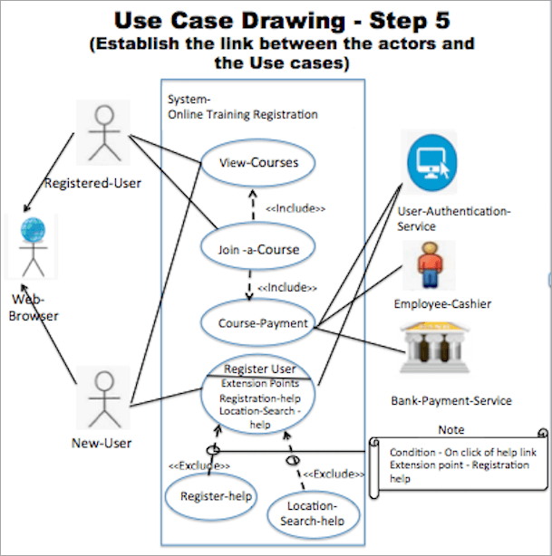
Step 5:
Establish the link between the actors and the Use cases. The column 'Allowed Actors/Multiplicity number of Actor' in 'List of Use Cases' section of the document gives all the actors to Use case association.
There can be some actor that is allowed by the Use case but they do not have any role in the current system being depicted. Like the actor 'Instructor' that can access use case 'View-Courses' but does not have a role in the current system being depicted.
This completes 'Online Training Registration' system depiction.
Use Case Diagram Examples
Example 1: This diagram represents a system named Student Management System that has five functionalities in scope.
There are two user roles, i.e. Actor who have access to the system. Actors, Teachers, and students have access to functionalities check time table, check grades and check attendance. The access to functionalities update attendance and update grades are only for actor Teacher.

[image source]
Example 2: This diagram represents Online Shopping System that has three independent functionalities in scope. Complete checkout and view items are two included functionality of Make purchase.
The primary actor is Customer and there are four supporting actors which are services like identity provider, service authentication, and external applications like PayPal, Credit payment service.

Example 3: This diagram represents a system Website that has 7 functionalities in scope. There are two Actors Webmaster and Site user. The Search Doc functionality has two included functionalities Preview doc and Download doc.
The Preview doc includes Browse doc functionality. There are two extension points one for each use case Upload doc and Add user.

Frequently Asked Questions
Q #1) What is the difference between use case diagram and use case?
Answer: Use case diagram depicts an application/system, its users, and use cases in the scope of the system. A use case represents one specific task to achieve a goal by a user that is in the scope of the system.
Q #2) What information is contained in a use case diagram?
Answer: This diagram summarizes the tasks in the scope of the system by detailing the tasks (use cases) and its users (actors). The details are presented pictorially, giving interactions between all the components presented.
Q #3) What is an example of a use case?
Answer: A use case describes the functionality of a process. Some example of business use case is system login, placing an online order, making payment, etc.
Q #4) What is included in the use case diagram?
Answer: It mainly consists of a system boundary with use cases, actors, and their relationships.
Q #5) Name a few UML diagram tools.
Answer: Some popular UML tools are – Lucid chart, EdrawMax, Moqups, Visual Paradigm, Sketchboard, Gliffy, Creately, SmartDraw.
Conclusion
The UML Use Case diagrams capture the dynamic nature of the system. They present all the users of the system and all the functionalities supported by the system. The functional requirements from the perspective of all internal and external users is captured and represented.
The first component of the Use Case diagram is the system scope called the system boundary or the subject. All the tasks covered under the system's subject are the use cases. The roles and services that have access to the functionalities considered under the specific system are called actors. The diagram depicts the relationship between use cases and actors.
Also Read =>> What is Use Case Testing
Thi diagram presents the functional requirement in an easy-to-understand way and helps in communication, clarity and facilitates tracking the development too.
A Use Case diagram simplifies the complex system and is very powerful as a picture is worth a thousand words!
Source: https://www.softwaretestinghelp.com/use-case-diagram-tutorial/
Posted by: dagnydagnydeboes0250935.blogspot.com